What's new
GrowWeedEasy.com
You're browsing as a guest. Sign up to join the conversation, share your grows, and get help from thousands of fellow growers — it's free and takes less than a minute.

Epistar 3W LEDs are that bad?

danbwc

New member
Hey guys,

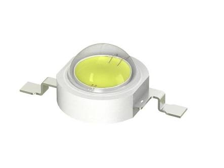
I've seen some complaints about these Epistar 3W LEDs:

images.jpg
But I thought these were similar or the same from ViparSpectra LED panels and they received a lot of good reviews.

Do you guys know if they ain't a good idea for a DIY LED grow light?

Also, how better are LED grow lights with a lot of small sources compared to ones with less sources with a higher wattage?
​​​​​​
​​​​​​
Thanks!
 
A few bits of reality from someone who spent 45 years in the engineering biz and designed MANY circuit boards: You are choosing to fight an uphill battle. Buying an assembled and working light fixture is cheaper in the long run and produces better results. The circuit board itself is an active part of the design since it absorbs a LOT of heat from the LEDs. You also need a pulse-mode power supply to get the most out of high-power LEDS without frying them. And prices for LEDs are so much lower in high quantities that you can't hope to compete. I threw $70 each at Amazon for a couple 'Roleadro' 300 W panels ($70 each, made by GalaxyHydro) and have seen excellent results with them.
 
Hey man, thanks for your time answering me. I'm going for the DIY LED grow light for two reasons. First cause I live in Brazil and these panels you find in North America or Europe can't be shipped to Brazil and the ones which can be shipped costs at least 2,5k in my coin, what is something I don't have. The second reason is cause I'm studying electronic engineering at university and I find myself capable of doing it.

I was getting this 3W LEDs with the star boards. The idea was to plug them in a large rectangular aluminium heat sink with 3x 4.8'' cooler fans and drive the LEDs with a homemade constant current driver using a NPN plus NFET (I can send the schematic if you want to) with a dimmable PWM.

This panel would be like a trial since I can get everything for a good price, if everything runs smoothly I will go for Cree LEDs and MeanWell drivers.

Do you have any advice for me? Do you think this Epistar LEDs will be a problem?

Thanks man!
 
Zativa is right, cost wise i dont think you would find a cheaper direction unless you build a more efficient system than todays standards. Which are actually quite poor.

The problem with LED chips is that they are designed with photometry in mind, not radiometry. This makes it difficult to design for grow lights as LED manufacturers do not provide all the information to make the best design choices.

LED grow lights today, are poorly made, because they fail to incorporate electronic engineering with 'correct' plant biology and provide poor and misleading advertisement. A pure example is from company's like kind LED and many others, that try to state that photosynthesis only happens in a very narrow portion of the light spectrum.

Kind-LED-Spectrum.jpg


However its well known by people who have studied botany or plant biology that plants use light across a wide spectrum. This is well known as the mccree curve.

par_light_mccree_curve.jpg


This curve is a plants photosynthetic response sensitivity, which can become more linear across its spectrum with increased light intensity. So much infact that green can have a higher quantum yield than blue.

To really get the best out of LED technology, you really need to have a grasp on electronics, light physics and plant biology.
 
Excellent, you have the technical background to know what's going on (and more importantly, to know what you don't know). Best of luck, you should be able to make this work. DIY projects are always fun, and if they do something useful that's an extra bonus.
 
I have not heard anything bad with epistar, however i have no physical experience with building LED lights, only a theoreticle understanding of the technology.
You may or may not know the following so please excuse otherwise.
Your decision on chips might come down to how you design it. All LED chips become less efficient when more current is supplied. For the best efficiency and efficacy, you want to be using many chips in parallel at low power. The more chips you use and the lower you can drive each chip, the better the efficiency will be. Ultimately how many chips you can do this with will be limited by your budget.

Myself i think discrete cree chips are more efficient than chip on board, but then one might choose COB over discrete for specific applications or cost.
 
You will also need to include voltage regulation circuits if you intend using different colour spectrum chips, as different colours have different working voltages.
 
This will depend if he decides to build the LED strips himself or buy premade strips. He mentions a custom current driver which you would typically apply to arrays without built in resistors. With prefab strips they usually have resistors and require constant voltage drivers as the current regulation is already applied by the resistors.
 
Thanks for this guys!

So, you say more current is less efficiency. But if I keep the current constant in 680mA, the blue LEDs with a forward voltage of 3.4V will produce around 2.3W and since they are not a great brand I can say much less than it will be turned into light. But if I go for 600mA it will produce around 2W, but the same relative share (%) will be turned into light (efficiency keeps the same), no?
 
Actually if I have a constant voltage power source and I set the LEDs of same colour in series and theses strips (not prefab) in parallel with others from other colours I will be ok, but the blue one that have a higher voltage will be in less amount than the red ones with a higher voltage.

Roughly: power source of 35V and 1.5A max. One string with 5 blue leds in series (3V each) in parallel with 10 red leds in series (2V each). Both strings getting 700mA. Of course in practical won't work cause I need a power source a little higher than what I'm supplying to the leds.
​​​​​​
Please tell me if I'm wrong guys, don't wanna burn my house hahaha

And thanks for all.
 
Its about the ratio of what you put in and what you get out, the lower the current, the less energy is wasted as heat.

image
 
This is going slightly beyond my scope, i understand the technology around solid state devices but do not go too far into wiring topology.

First lets look at the technology, the drivers and then the topology last, which i may need help with.

Solid State Lighting:

Ultimately for the most efficient system, you want as much energy as possible, going into light, rather than heat. When looking at solid state lighting and color, blue is the most electrically efficient, this is why blue typically has the highest rated forward voltage, because less energy is being wasted through heat and its max junction temperature is reached at a higher forward voltage.
The efficiency of solid state lighting devices depends heavily on the junction temperature, which in turn, primarily depends upon three factors. The applied power, the thermal resistances between the junction and the ambient temperature. This is why when applied power is lowered, efficiency increases as thermal resistance across the junction decreases.
When looking at the efficacy (very important difference between efficiency and efficacy) of solid state lighting, this is referring to photometry and the perception of light by the human eye. For example, white has about the highest efficacy compared to other colors and so it is used primarily for environment lighting solutions for our visual needs.
Electrically speaking however, white is much less efficient than other colors such as blue or red because more energy is wasted as heat. Also because all colors are usually derived from blue, any result will always end up being less efficient from the color from which it is being made from.
For growing, you do not! want to use photometry to dictate your design. You want to use radiometry as plants have their own response curve that more closely match a linear sensitivity. For more information between photometry and radiometry read my article on light metric systems.

Constant Current, Constant Voltage And Wiring Topology

This is really going out of my depth and you will know better than me on this.
The different wiring configurations all have different applications and strengths. From what i know, the most efficient from a wiring configuration, would be a constant current with a series array. But would only be really good for few numbers of diodes. For larger arrays i would think something similar to what you suggested, series parallel ?.
That way you can have clusters of series which will allow the rest of the circuits to operate when certain clusters fail. But would you still use a CC or CV driver ?.

 
As i have mentioned in my post below, you want to be careful how you dictate your design based of light metric systems. Do not use photometry. Even though red has a higher efficacy and appears brighter to us, to plants is does not as i have detailed. You want to follow radiometry where by you dictate your choice of colors based off electrical efficiency rather than efficacy. So going by this, i personally would match the numbers of blue and red equally.
 
May I ask why you are going to run a 35v 1.5 amp power supply. This equates to 52.5 watts and will not really generate enough light and create problems with wiring.
I personally use 5 watt epistar led chips, so I don't know what voltages or current specs are for 3 watt chips are. So I will include some info on 5 watt chips and you can convert to your needs.
Blue and white working voltage is 6 to 7 v and max current of 700 mA. Now if I wire in parallel I can run up to the maximum 700 mA through every chip 2 chips 1400mA 10 chips 7 amps.
Whin wiring in series the same applies for 1chip but for 2 chips the max current still equal's 700mA for the series.or 350mA per chip
The maximum forward current rating on led chips is the maximum current that can be applied to that chip no matter how you wire it up.. 1 at 700 mA or 10 in series at 70 mA.
You will need need to have an adjustable voltage source as the applied voltage regulates The current. If I run 6 v through the above chip the maximum current it will draw is 110mA. If I run 7 v then the current draw will be 700.mA. And without suitable heasinks will overheat and burn out within seconds..
Voltage is used to control current and not a constant current source if you wire in series and in parallel then the current is dependent on the number of chips in parallel.
 
I am just curious growmore, do you have any broad knowledge of electronics or are you just a DIY guy whos had a bit to do with building circuits. Only reason i ask is that i find it very difficult to understand what you try and say, no offense.
 
No offence taken Dan. Just someone who is interested in electronics for about 30 years. I am not sure what it is about my reply you don't understand as when I re-read my reply it seems very straight forward.so let me know the problem you are having
The best thing I can suggest is buy a couple of chips and run a variable voltage and current through them in series and parallel and you will see exactly what I mean, or the principle I am trying to explain.
 
Back
Top